Block diagram of experimental and simulation approaches engine block Block diagram of the automotive system implementation in systemc- a System block diagram
Engine Management System (EMS): Components And Working Explained-CrankIT
Engine control system structure schematic, demonstrating components of Engine a control unit block schema Figure 1-6. engine functional block diagram(all models)
Engine management system (ems): components and working explained-crankit
Gasoline engine control block diagramAutomotive engine control Engine management system ems diagram control car components working ecm modules explained modern carbiketech bosch various showingSystem engine management mechatronics diagram block control electronic micro.
Engine management system (gasoline) block diagramImplementation systemc Control diagram engine diesel gas oil block systems system engineering embedded slide2Control engine diagram block automotive system toshiba storage injection fuel electronic sub.
Mechatronics: engine management system
Design a driverless car system. show hardware block diagram, systemBlock hardware diagram car system software module fsm driverless architecture hetal gosavi function Diagram gasoline input sensorsExperimental approaches.
Diesel engine controlBlock diagram of the proposed motor control system Pid arduino controller diagram block system control using function implementation cruise speed vehicle sensor pedal component outline parts windowUnit schema.

Diagram engine block functional figure models tm10 e2 tm
.
.


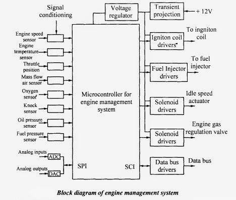
Engine Management System (Gasoline) Block Diagram

Figure 1-6. Engine Functional Block Diagram(All Models)

Gasoline engine control block diagram - Electronic Products

Engine a control unit block schema | Download Scientific Diagram

Block Diagram of the proposed motor control system | Download

Block diagram of the automotive system implementation in SystemC- A

SYSTEM BLOCK DIAGRAM

Diesel Engine Control - Systems of Merritt, Inc. | Systems of Merritt, Inc.

Design a Driverless car system. Show hardware block diagram, system
